


Our range includes the most sturdy systems for grain drying on the market. We deliver fuel storages, and also transfer- and burner devices for fuel for the most known drying furnaces in the market.
Our burners are compatible with, for example, the following bio furnaces:
- MEPU
- ARSKA
- ANTTI-TEOLLISUUS
Heating-plant components and operational description:
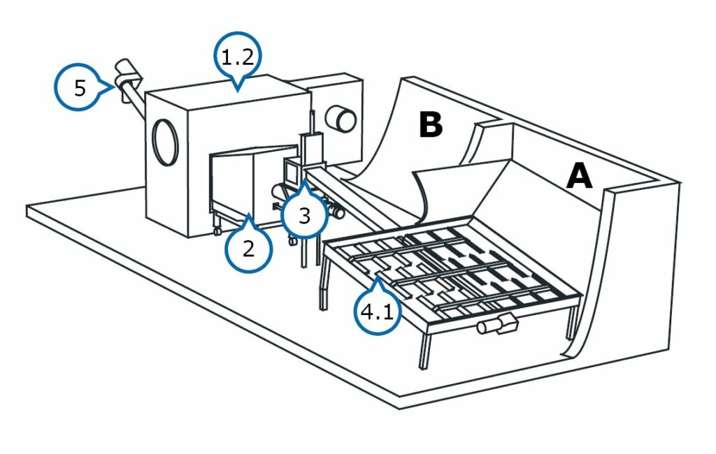
A – Fuel storage
B – Boiler room
1.2 Drying furnace
2. Burner
3. Feed hopper
4. Hydraulic feeder
5. Ash removal
6. Ash receptacle (not pictured)
7. Flue gas fan
8. Chimney
The feeder (4.1) made of steel to be installed at the bottom of the fuel storage, is equipped with efficient hydraulically operated pull bars.
The bars pull the fuel to the conveyor screw at the centre of the storage. The trough conveyor transports the fuel to an feed hopper (3), which is equipped with a hydraulically operated closing hatch. The level of the feed hopper is monitored, using an ultrasound sensor.
The fuel is fed from the feed hopper, using a screw conveyor, to the combustion end of the burner (2). Burning occurs in the combustion end and the flame is conducted inside the furnace. The automation adjusts the burning steplessly. If needed, the fuel supply and combustion-air fans will react quickly to the fluctuation of power requirements by increasing or decreasing the power. The heat is transferred from the convection surfaces of the furnace (1.2) to the drying air, which is kept at a consistent temperature maintained by using the PT-100 measurement.
The burned out fuel is pushed out as ash into the furnace’s ash space with the help of the hydraulically moving grate aggregate. The ash is transported with screw conveyors (5) into a large ash receptacle (6) located outside the building.
The vacuum-controlled flue gas aspirator keeps the furnace’s vacuum, i.e., draught, as desired, thus enabling the use of a wide power range.