


Pull bar storage heating plants are suitable for power categories 60–800 kW. These allow use of a maximum fuel-storage size of 70 m3.
- For agricultural heating needs
- For heating of properties
- Heating containers
Heating-plant components and operational description
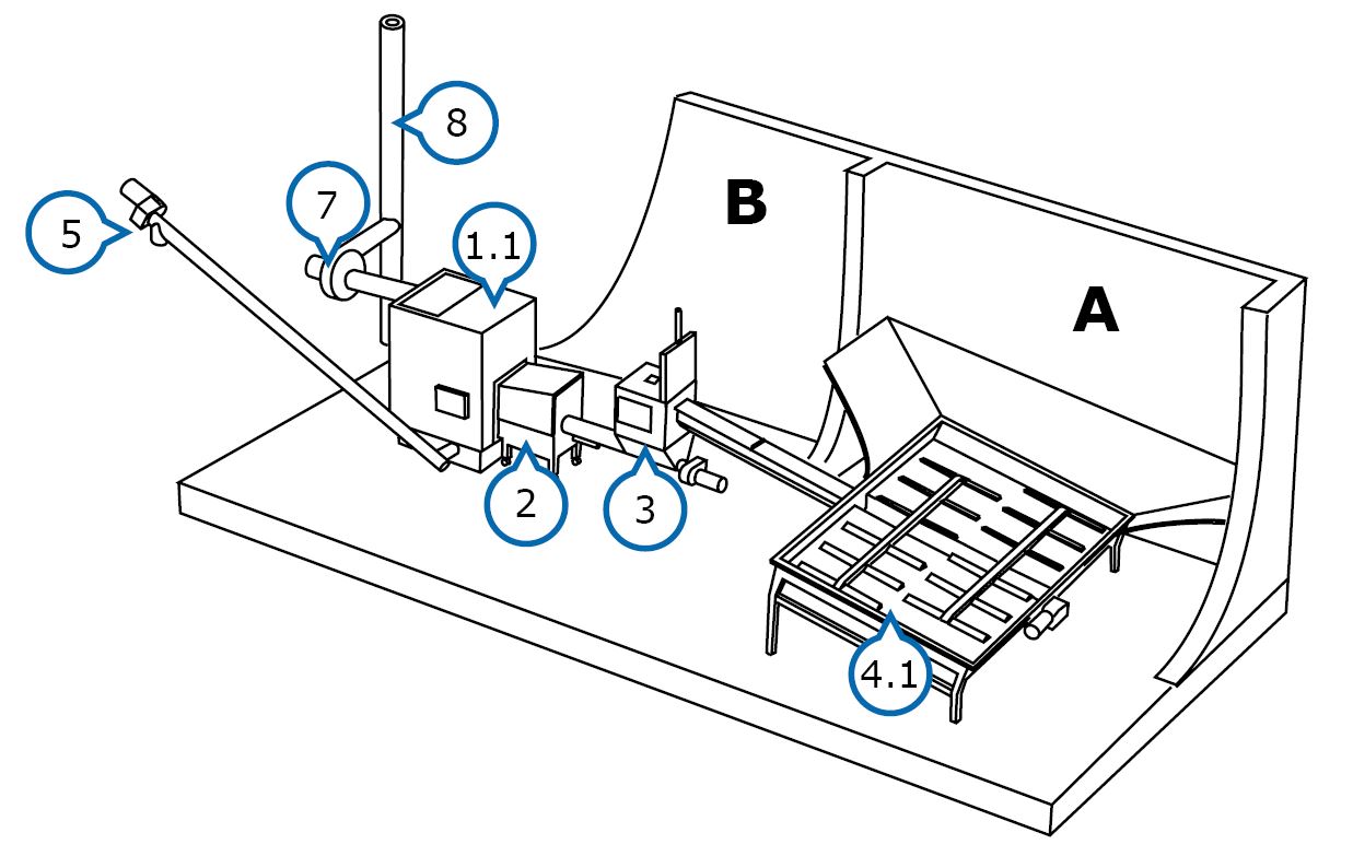
A – Fuel storage
B – Boiler room
1.1 Boiler
2. Burner
3. Feed hopper
4. Hydraulic feeder
5. Ash removal
6. Ash receptacle (not pictured)
7. Flue gas fan
8. Chimney
A system in accordance with EN303-5 standard. The feeder (4.1) to be installed at the bottom of the fuel storage is equipped with efficient, hydraulically operated pull bar feeder.
The bars pull the fuel to the conveyor screw at the centre of the storage. The trough conveyor transports the fuel to an feed hopper (3), which is equipped with a hydraulically operated closing hatch. The level of the feed hopper is monitored, using an ultrasound sensor.
The fuel is fed to the combustion end of the burner (2) from the feed hopper, using a screw conveyor. Burning occurs in the combustion end and the flame is conducted inside the boiler (1.1). The automation adjusts the burning steplessly. If needed, the fuel supply and combustion-air fans react quickly to the fluctuation of power requirements by increasing or decreasing the power. The combustion air is controlled, using precise air-flow regulators and LAMBDA measurement. The heat is transferred from the boiler’s convection surfaces to the boiler water, which is kept at a consistent temperature maintained by using the PT-100 measurement.
The burned out fuel is pushed out as ash into the boiler’s ash space with the help of the hydraulically moving grate aggregate. The ash is transported with screw conveyors (5) into a large ash receptacle (6) located outside the building.
The vacuum-controlled flue gas fan (5) keeps the boiler’s vacuum, i.e., draught, as set, thus enabling the use of a wide power range.