


Biofire is a strong operator as a supplier of industrial-grade heating plant systems. Due to the large fuel need, the wood chips are fed by using a drag-chain conveyor (a larger feed capacity than with the screw conveyor)
- For heat suppliers
- For municipalities
- For district heat production
- For process heating

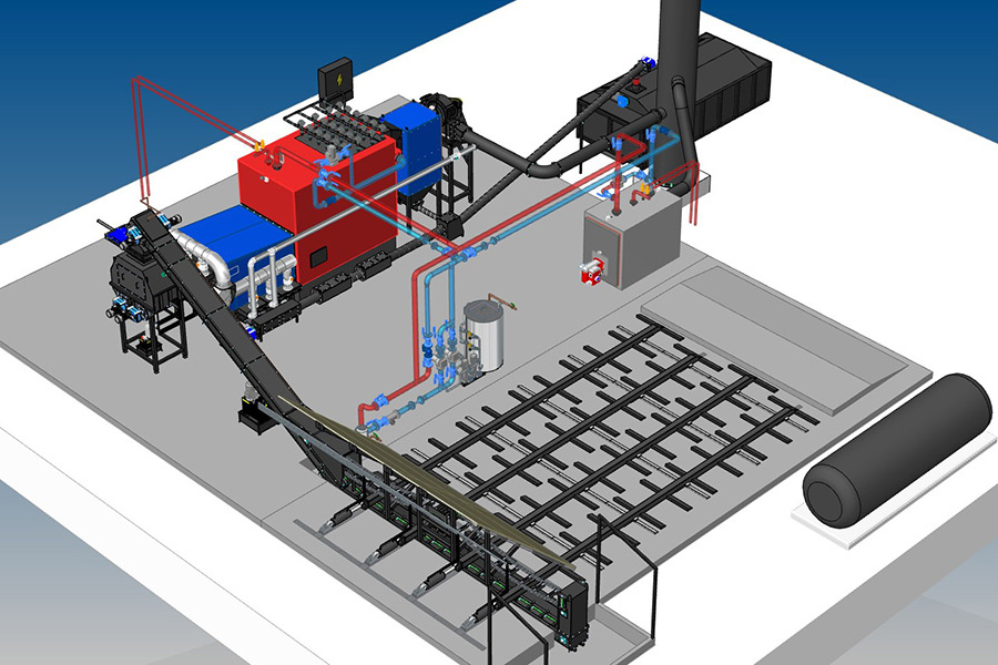
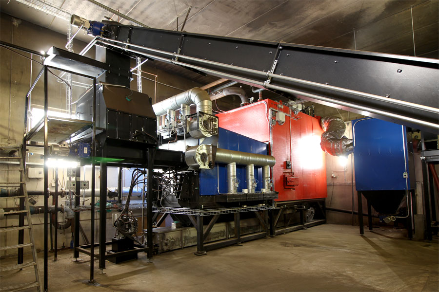
Heating-plant components and operational description
Heating plant with dry-ash removal
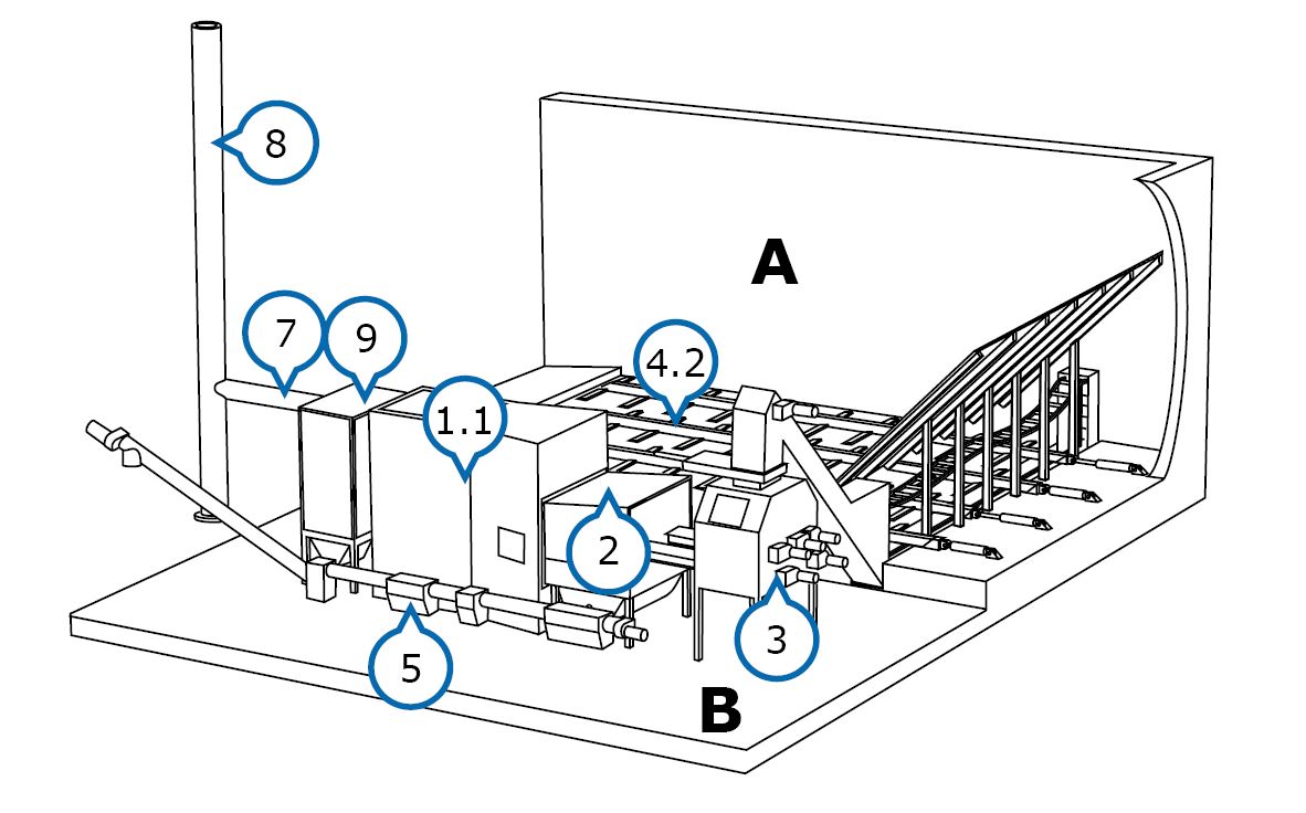
A – Fuel storage
B – Boiler room
1.1 Boiler
2. Burner
3. Feed hopper
4. Pull bar feeder storage
5. Ash removal
6. Ash receptacle (not pictured)
7. Flue gas fan
8. Chimney
9. Cyclone cleaner
Heating plant with wet-ash removal
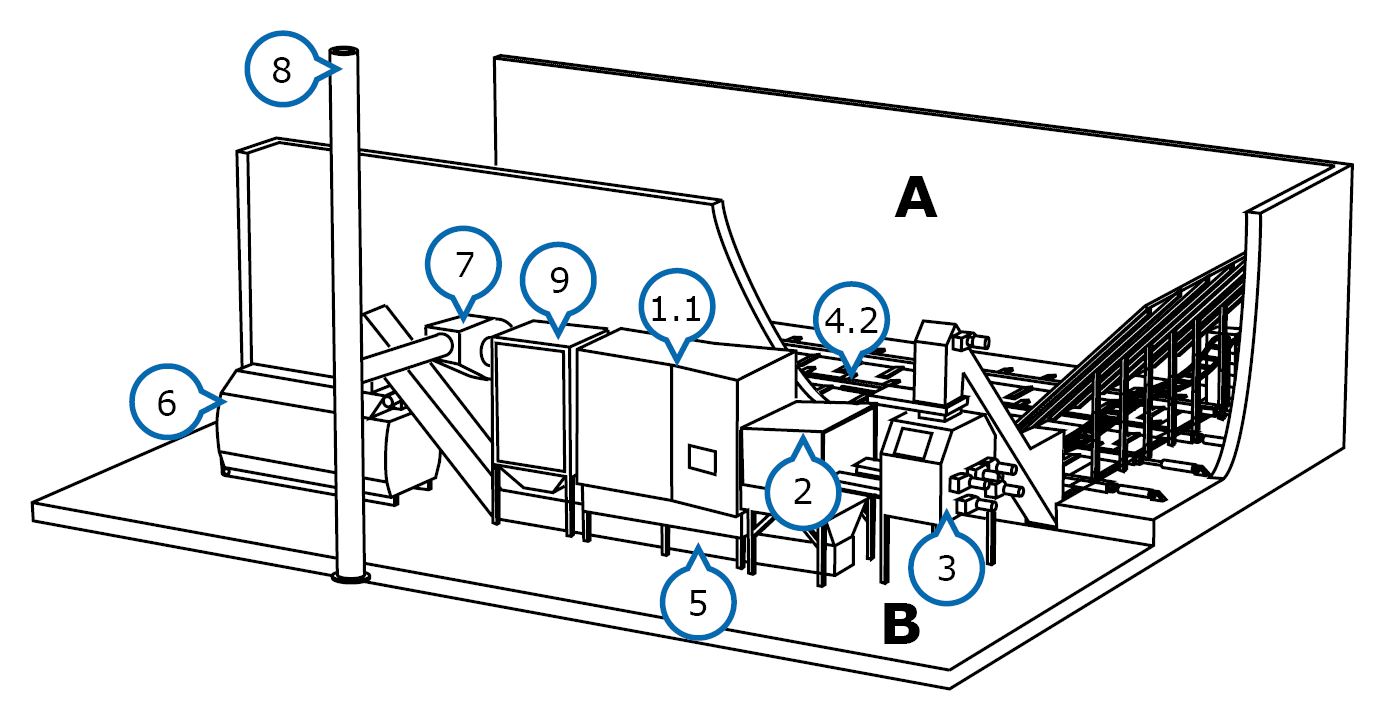
A – Fuel storage
B – Boiler room
1.1 Boiler
2. Burner
3. Feed hopper
4. Pull bar feeder storage
5. Ash removal (wet ashing)
6. Ash receptacle
7. Flue gas fan
8. Chimney
9. Cyclone cleaner
A system in accordance with EN303-5 standard. The sturdy and especially strong hydraulically operated pushrod unloaders (4.2) are placed on the floor of the fuel storage where anchoring irons have been installed during the concrete casting to reinforce the structure.
The bars pull the fuel onto the drag-chain conveyor and the feed hopper(3), which is equipped with a hydraulically operated closing hatch. The level of the intermediate tank is monitored, using an ultrasound sensor.
The fuel is fed from the feed hopper, using a screw conveyor, to the combustion end of the burner (2). Burning occurs in the combustion end and the flame is conducted inside the boiler (1.1). The automation adjusts the burning steplessly. If needed, the fuel supply and combustion-air fans react quickly to the fluctuation of power requirements by increasing or decreasing the power. The combustion air is controlled, using precise air-flow regulators and LAMBDA measurement. The heat is transferred from the boiler’s convection surfaces to the boiler water, which is kept at a consistent temperature maintained by using the PT-100 measurement.
The burned out fuel is pushed out as ash into the boiler’s ash space or into wet-ashing with the help of the hydraulically moving grate aggregate. The cyclone cleaner (9) separates the pulverized fuel ash efficiently, and the ash is then routed to ash removal. The ash is transported by using screw conveyors (5) in systems equipped with dry-ash removal into a large ash receptacle (6) outside the building. In systems using wet-ash removal, the ash is transported by using a drag-chain conveyor (5) into an ash container (6) placed inside the heating plant.
The vacuum-controlled flue gas fan (7) keeps the boiler’s vacuum, i.e., draught, as desired, thus enabling the use of a wide power range.