


A heating container with an integrated storage includes a boiler room and a fuel storage successively in the same assembly. The storage section has a hydraulically closing roof, and a hydraulic feeder has been installed at the bottom of the section.
The dosing equipment for the fuel supply, the burner, boiler, ash-removal equipment, and the automation are located in the boiler room.
A ready-to-use heating container is a practical option, because the ground work for construction is minor, when compared to a separate heating plant. It is sufficient when an even slab is cast as a foundation for the container beforehand, and heat-transfer canals, a water pipe and electricity are supplied on site. Connecting a container operational only takes a few hours.
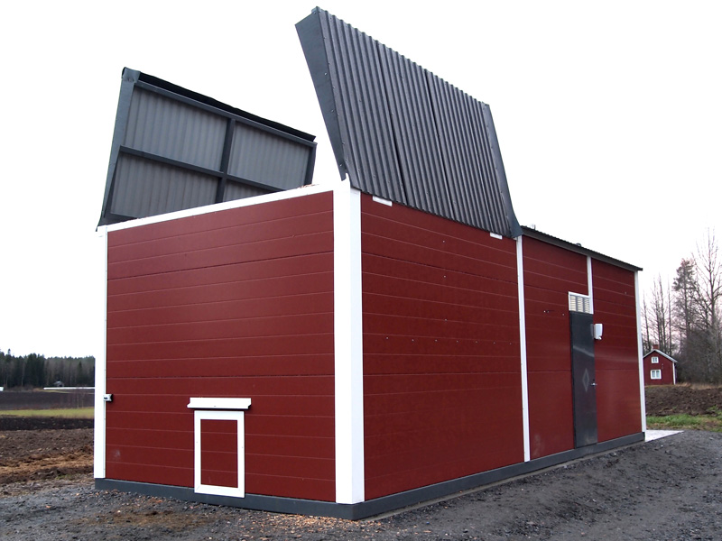
The storage section has a hydraulically closing roof.
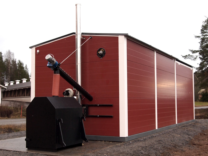
Ash removal and the chimney are situated at the end of the container.
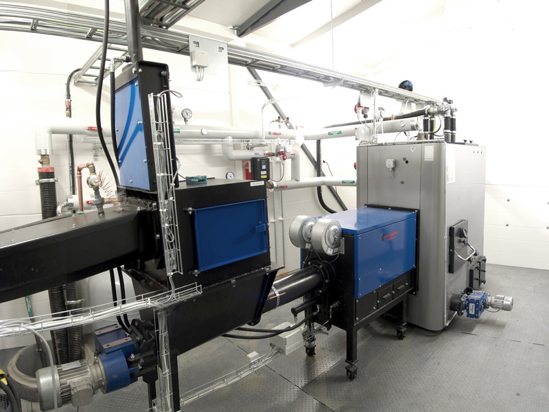
As a whole, the boiler room and device assembly is a system in accordance with EN303-5 standard.
Container components and operational description
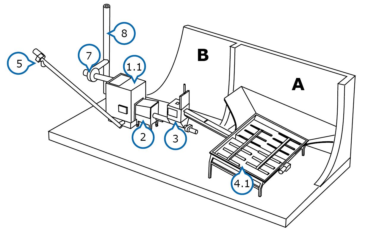
A – Fuel storage
B – Boiler room
1.1 Boiler
2. Burner
3. Feed hopper
4. Hydraulic feeder
5. Ash removal
6. Ash receptacle (not pictured)
7. Flue gas fan
8. Chimney
A system in accordance with EN303-5 standard. The heating container includes a boiler room (B) and a fuel storage (A) in the same overall unit. The storage section has a hydraulically closing roof.
The bottom-discharger (4.1) made of steel to be installed at the bottom of the fuel storage is equipped with efficient, hydraulically operated pushrod unloaders. The pushrod unloaders pull the fuel to the conveyor screw at the centre of the storage. The trough conveyor transports the fuel to an intermediate tank (3), which is equipped with a hydraulically operated closing hatch. The level of the intermediate tank is monitored, using an ultrasound sensor.
The fuel is fed from the intermediate tank, using a screw conveyor, to the combustion end of the burner (2). Burning occurs in the combustion end and the flame is conducted inside the boiler (1.1). The automation adjusts the burning steplessly. If needed, the fuel supply and combustion-air fans react quickly to the fluctuation of power requirements by increasing or decreasing the power. The combustion air is controlled, using precise air-flow regulators and LAMBDA measurement. The heat is transferred from the boiler’s convection surfaces to the boiler water, which is kept at a consistent temperature maintained by using the PT-100 measurement.
The burned out fuel is pushed out as ash into the boiler’s ash space with the help of the hydraulically moving grate aggregate. The ash is transported with screw conveyors (5) into a large ash receptacle (6) located outside the building. The vacuum-controlled flue gas aspirator (5) keeps the boiler’s vacuum, i.e., draught, as desired, thus enabling the use of a wide power range.